Clamp demand
Total every pressure-exposed projected area, state the cavity-pressure basis, alloy, slide effects, quality risk, and margin. Compare the signed result with 13,000 kN.
Evidence: calculation sheet
DC1300T / Heavy-cell engineering blueprint
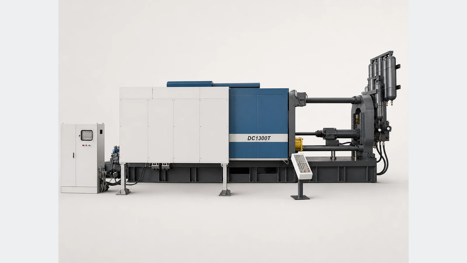
The DC1300T is a 13,000 kN cold chamber platform for large aluminum and magnesium projects. Its value depends on more than clamp force: the casting, complete shot, die movement, thermal process, automation, building services, acceptance evidence, and supply boundary must resolve into one buildable production-cell plan.
Published DC1300T data reviewed August 10, 2026 by Cathy, Director. Final approved drawings and the signed technical agreement govern the supplied configuration.
Blueprint 01 / Model-fit logic
Engineering, tooling, automation, plant, quality, and purchasing should work from the same controlled inputs. A red condition in any lane keeps the model open; a green result in all six lanes supports a defensible technical shortlist.
Total every pressure-exposed projected area, state the cavity-pressure basis, alloy, slide effects, quality risk, and margin. Compare the signed result with 13,000 kN.
Evidence: calculation sheetInclude all castings, runners, biscuit, overflows, and process allowance. Verify weight and required intensification pressure against one exact shot-end package.
Evidence: mass balanceCheck width, height, 450-1,200 mm thickness, weight, mounting, opening, ejection, slides, core pulls, cooling, vacuum, lifting, and changeover.
Evidence: interface drawingDefine fill profile, velocity, pressure, thermal control, vacuum, spray, metal temperature, die temperature, quality criteria, inspection, and traceability.
Evidence: process basisFreeze cycle definition, annual volume, shifts, OEE assumptions, furnace, dosing, extraction, trim, conveyors, inspection, scrap routing, and recovery logic.
Evidence: time studyApprove transport, lifting, foundation, utilities, safety, service zones, destination rules, FAT, SAT, documentation, training, spares, and warranty ownership.
Evidence: project execution planBlueprint 02 / Pressure-capacity envelope
The manufacturer publishes boundary ranges for the DC1300T rather than a complete set of paired values. Do not interpolate those values into a purchase decision. Ask the quotation to state aluminum and magnesium capacity, intensification pressure, casting area, sleeve dimensions, and injection position for every offered plunger diameter.
The approved package must clear complete shot while preserving the required intensification pressure and agreed process margin.
Confirm the exact offered diameters and sleeve interfaces.
Use complete shot, not net casting weight.
Confirm alloy basis and real process allowance.
Published pressure decreases toward the capacity-led end.
Geometry and cavity pressure still govern actual fit.
Blueprint 03 / Controlled data sheet
These published values support model screening and RFQ preparation. Final approval requires project-specific datums, tolerances, component schedules, interface drawings, utility loads, foundation information, and the signed technical agreement.
Source: current manufacturer-published DC1300T data, reviewed August 10, 2026 by Cathy, Director | *Confirm injection-position datums and available settings in the approved drawing | Signed technical documents take precedence.
Published manufacturer reference: ShiMi DC1300T Standard Cold Chamber Die Casting Machine. Use this public record to cross-check the web summary; approved supplier drawings and the signed technical agreement govern the final configuration.
Blueprint 04 / Maintainability review
These official system references have been cleaned of Chinese and brand text. They show typical component families and access questions, not a guarantee of the final make, quantity, layout, color, or included scope.
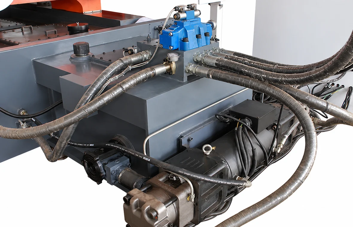
Use the interface review to freeze component makes, filtration, oil grade, temperature limits, cooling duty, isolation method, hose and seal spares, diagnostic points, lifting access, safe maintenance zones, and the drawings delivered for the installed circuit.
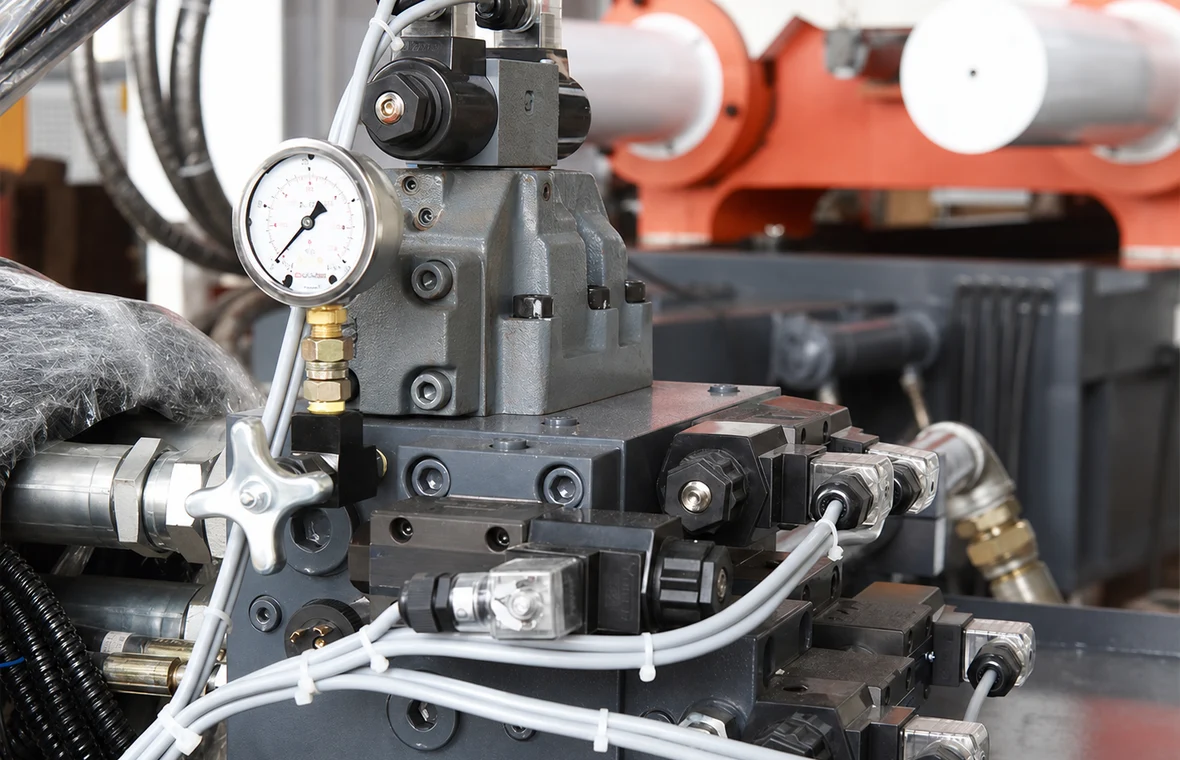
The signed test plan should state calibration points, pressure and velocity measurements, accumulator discharge procedure, repeatability sample, alarm and interlock checks, replacement parts, data format, and the exact pass criteria used during FAT and SAT.
Blueprint 05 / 95 ton site plan
The published 11 x 4.0 x 4.5 m dimensions describe the base machine. Furnace, dosing, spray, extraction, trim, guarding, platforms, piping, die handling, access, and maintenance zones expand the final footprint and connected loads.
Freeze packing split, transport dimensions and weights, port and road limits, unloading equipment, doorway and aisle clearance, floor transitions, center of gravity, lifting points, crane capacity, hook height, rigging, and final-positioning responsibility.
Approve floor load, pits, anchors, leveling, grout, drainage, oil containment, vibration criteria, crane coverage, die-change route, storage, tie-bar and platen service, accumulator access, electrical-panel clearance, and safe escape paths.
State voltage, frequency, transformer and cable boundary, connected and operating demand, cooling-water flow, pressure and quality, compressed air, oil cooling, furnace energy, exhaust, network, connection locations, and local distribution ownership.
Define applicable standards, risk-assessment responsibility, guarding, interlocks, emergency zones, stairs and platforms, lockout points, hot-metal hazards, operator sightlines, labels and language, validation records, environmental obligations, and permits.
Blueprint 06 / Execution sequence
A large machine order needs a controlled information flow. Each gate should end with approved documents, named owners, open-action dates, and a clear rule for proceeding, holding, or changing scope.
Approved casting basis, clamp calculation, complete shot, shot end, die interfaces, process requirements, cell scope, safety concept, utilities, and exclusions.
Release: signed specificationGeneral arrangement, foundation, interfaces, component schedules, electrical and pneumatic diagrams, I/O, risk review, service access, and document register.
Release: approved drawingsSafety, motion, die protection, injection stages, pressure build, repeatability, alarms, recipes, interfaces, sample conditions, records, pass criteria, and open actions.
Release: FAT recordPacking, shipment, unloading, positioning, installation, commissioning, production trial, capability evidence, training, manuals, backups, spares, warranty start, and final handover.
Release: acceptance certificateBlueprint 07 / Commercial normalization
Require each bidder to mark every line Included, Optional, By Buyer, or Excluded, with a technical reference and price effect. This makes hidden integration work, lifecycle costs, and commissioning risks visible before order placement.
Selected shot end, controls, hydraulics, core pulls, lubrication, cooling interfaces, guarding, die protection, options, component makes, oil charge, colors, certifications, and exclusions.
Furnace, dosing, spray, extraction, quench, trim, conveyors, scrap, inspection, vacuum, thermal control, I/O, recipes, traceability, network, safety integration, and cycle ownership.
Incoterm, packing, insurance, freight, unloading, foundations, piping, cabling, installation, commissioning, sample material, production support, local labor, permits, and utilities.
Drawings, manuals, certificates, software, backups, FAT and SAT records, training, translations, included and recommended spares, warranty, remote support, service response, and escalation path.
Blueprint 08 / Procurement FAQ
Use these answers for early screening, then place project values, calculations, drawings, responsibilities, tolerances, test conditions, and acceptance evidence into the signed technical agreement.
The DC1300T is an initial candidate for large aluminum or magnesium projects whose verified clamp demand, complete shot, die envelope, pressure requirement, automation, and plant interfaces fit the published 13,000 kN platform. The 1,300 ton name does not approve a casting or justify unused capacity without calculations.
Published data lists 13,000 kN clamping force, 1,000 mm clamping stroke, 550 kN ejecting force, 200 mm ejection stroke, 450-1,200 mm die thickness, 1,730 x 1,730 mm platens, 1,100 x 1,100 mm tie-bar spacing, 1,100 kN injection force, 910 mm injection stroke, 75 kW motor power, a 2,000 L oil tank, and approximate 95 ton machine weight.
Published ranges cover 100-140 mm plunger diameters, 13-36 kg aluminum shot, 9.3-18.7 kg magnesium shot, 140-71 MPa intensification pressure, and 885-1,735 cm2 casting area. Request the exact paired values for every offered diameter, then select against complete shot and required pressure together.
Total the pressure-exposed projected area of all cavities, runners, overflows, and slides, multiply by the agreed cavity-pressure basis, and apply the documented operating margin. Check the result against 13,000 kN separately from shot capacity, die fit, and the published 3,125 cm2 maximum casting area.
Approve the shipping split, transport and unloading route, lifting equipment, center of gravity, foundation, anchoring, floor load, 11 x 4.0 x 4.5 m bare-machine envelope, die-change route, crane coverage, maintenance zones, electrical supply, cooling water, air, exhaust, oil cooling, guarding, and every peripheral footprint from final drawings.
Require the selected shot end, controls, hydraulics, core pulls, cooling and vacuum interfaces, automation ownership, safety scope, utilities, drawings, manuals, software backups, spares, packing, installation, training, warranty, and exclusions. FAT and SAT should define test conditions, measurements, records, pass criteria, corrective actions, and retest responsibility.
DC1300T project-input package
A useful response should identify model fit, the exact shot-end package, die and automation interfaces, preliminary factory requirements, acceptance path, commercial boundary, open assumptions, and the owner of each next action.
Alloy, drawings, projected area, cavity-pressure basis, cavities, net weight, runners, biscuit, overflows, complete shot, fill, quality, inspection, and traceability.
Dimensions, thickness, weight, mounting, opening, ejection, slides, core pulls, cooling, vacuum, lifting, storage, and changeover method.
Cycle definition, annual volume, shifts, OEE basis, furnace, dosing, spray, extraction, quench, trim, inspection, scrap, guarding, I/O, data, and recovery.
Layout, route, foundation, crane, utilities, safety standard, destination, Incoterm, FAT, SAT, documents, installation, training, warranty, and spares.