- Aluminum shot
- 3.0 kg
- Magnesium shot
- 2.2 kg
- Intensification pressure
- 145 MPa
- Published casting area
- 320 cm²
Highest listed pressure; lowest complete-shot allowance.

DC400T / Medium cold chamber production platform
The DC400T combines a listed 4,000 kN clamp, a 700 × 700 mm die opening, and three shot-end choices for aluminum and magnesium production. Approve it as a complete manufacturing platform only after clamp demand, complete shot, die movement, process pressure, automation, utilities, and acceptance scope are documented together.
Published DC400T data reviewed August 9, 2026 by Cathy, Director. Final approved drawings and signed technical documents take precedence.
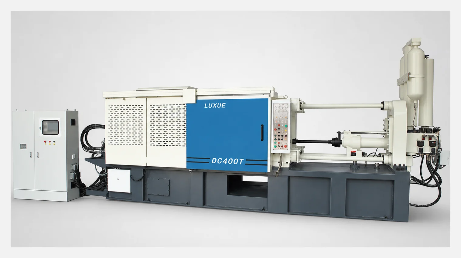
Model approval brief
Purchasing can compare price, but engineering must first confirm that the same casting and process assumptions pass four independent boundaries. A larger nominal tonnage cannot compensate for an unsuitable shot package, die interface, or cell layout.
Review the machine RFQ checklist →Consider the DC400T when calculated clamp demand stays inside 4,000 kN with the agreed margin, complete metal demand fits one confirmed pressure-capacity package, the die and all movement clear the published envelope, and the complete production cell can be installed, guarded, operated, and maintained at the destination factory.
Total cavities, runners, overflows, and pressure-exposed slides. Record alloy, cavity pressure, fill requirement, quality risk, and operating margin.
Include biscuit and process allowance; verify die width, height, thickness, weight, opening, ejection, core pulls, cooling, vacuum, and lifting.
Define furnace and dosing, spray, extraction, trim, scrap handling, inspection, changeover, target cycle, shifts, annual output, and recovery sequence.
Confirm floor loading, access route, power, water, air, exhaust, safety standard, documentation, FAT, packing, installation, training, service, and spares.
Shot-end decision lanes
The published 60, 70, and 80 mm packages link metal capacity, intensification pressure, and casting area. The largest package is not automatically safer: capacity increases as listed pressure decreases.
Highest listed pressure; lowest complete-shot allowance.
Middle package for a balanced pressure-capacity requirement.
Largest listed shot allowance; lowest listed intensification pressure.
Actual allowable projected area depends on the agreed cavity pressure, pressure-exposed geometry, alloy, quality target, and operating margin. Complete shot demand and die fit remain separate checks.
Engineering control sheet
These published values support initial comparison and RFQ preparation. Confirm reference datums, tolerances, component brands, selected options, interfaces, and installation dimensions in the approved technical package.
Technical reference: current published DC400T product data, reviewed August 9, 2026 by Cathy, Director | *Confirm injection-position datum and usable range in the project drawing | Final signed technical agreement takes precedence.
Published manufacturer reference: ShiMi DC400T Standard Cold Chamber Die Casting Machine. Use this public record to cross-check the web summary; approved supplier drawings and the signed technical agreement govern the final configuration.
System evidence
These official system references have been cleaned of Chinese text. They show component families and access areas, not a promise that every visible brand, quantity, or arrangement is included in the final DC400T scope.
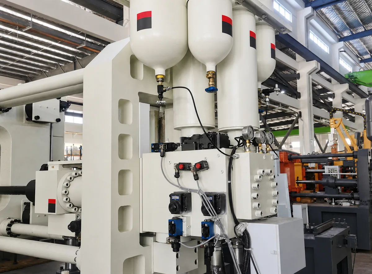
The published configuration describes separate high-speed and intensification accumulators. Define pressure verification, safe discharge, inspection intervals, gauge accuracy, acceptance evidence, and critical spares in the technical agreement.
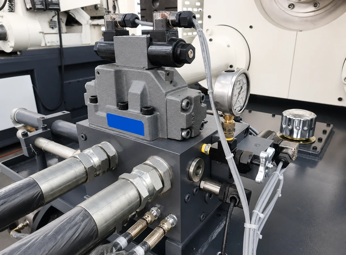
Record the quoted component makes, filtration and oil requirements, core-pull groups, service access, diagnostic points, hose and seal spares, and the maintenance documents delivered with the machine.
Production-cell responsibility map
Comparable quotations identify the owner, interface, acceptance evidence, utilities, documentation, and exclusions for every system around the DC400T.
Capacity, energy source, temperature control, alloy change, transfer height, ladler or dosing method, loss assumptions, signals, and safety.
Cooling circuits, die temperature, vacuum, spray, core pulls, clamping, ejector interface, lifting, changeover, and leak testing.
Robot or extractor reach, gripper, part confirmation, quench, conveyors, trim, scrap, marking, inspection, reject routing, and cycle recovery.
Voltage and frequency, cooling water, air, exhaust, floor and foundation, access, guarding, safety standard, language, and maintenance space.
Recipe storage, user levels, alarms, curve or process data, automation I/O, network boundary, backups, file formats, and remote support.
FAT method, sample materials and die, corrective actions, packing, lifting, installation, commissioning, training, warranty, service, and spares.
Factory acceptance sequence
A useful FAT plan is agreed before testing. It states the instruments, limits, sample conditions, records, attendees, pass criteria, and corrective-action process instead of relying on a general statement that the machine ran.
Check emergency stops, guards, interlocks, pressure release, labels, electrical protection, approved drawings, manuals, backups, and parts lists.
Observe opening and clamping stages, low-pressure die protection, ejection, lubrication, core-pull logic, alarms, access, and recovery.
Verify the selected shot package, slow and fast stages, pressure build, positions, recipes, gauges, repeatability evidence, and trace files.
Test automation signals and faults; reconcile included equipment, loose items, spares, preservation, packing, lifting points, training, and open actions.
DC400T procurement FAQ
Use these answers to keep purchasing, process, tooling, automation, maintenance, and plant teams working from the same approved project inputs.
The DC400T is an initial candidate for medium aluminum or magnesium projects whose total projected-area calculation, complete shot demand, die envelope, pressure requirement, and cell interfaces fit the listed 4,000 kN clamp and a confirmed 60, 70, or 80 mm plunger package. The 400 ton name is not a substitute for these checks.
Published data lists 4,000 kN clamping force, 550 mm clamping stroke, 265 kN ejecting force, 125 mm ejection stroke, 250-700 mm die thickness, 1,050 x 1,050 mm platens, 700 x 700 mm tie-bar spacing, 405 kN injection force, 570 mm injection stroke, a 22 kW motor, and an approximate machine weight of 17 tons.
Match complete shot weight and required intensification pressure together. The published aluminum allowances increase from 3.0 to 5.1 kg as plunger diameter rises, while listed intensification pressure decreases from 145 to 82 MPa. Select from the required process window rather than choosing the largest plunger automatically.
Calculate the projected area of every cavity, runner, overflow, and pressure-exposed slide, multiply by the documented cavity-pressure assumption, then apply the agreed operating margin. Check that result against 4,000 kN separately from shot capacity, die fit, and the published maximum casting area.
Compare the DC300T when it satisfies the project with margin and a smaller installed scope. Review the DC550T or DC880T when clamp demand, complete shot, the 700 x 700 mm die opening, 700 mm maximum die thickness, die handling, automation reach, or maintenance clearance crosses a documented DC400T boundary.
The quotation should state the selected shot package, controls, hydraulic components, core-pull groups, die interfaces, furnace and dosing equipment, spraying and extraction automation, guarding, utilities, spares, documents, packing, installation, training, and exclusions. FAT criteria should cover safety, motion, pressure and speed, alarms, recipes, interfaces, documentation, and corrective-action rules.
DC400T configuration and cell inquiry
A useful reply can address clamp demand, shot package, die movement, system interfaces, factory conditions, acceptance method, commercial scope, and unresolved risks together.
Casting and process Alloy, drawing, projected area, complete shot, cavities, pressure assumption, quality and traceability target.
Die and movement Dimensions, thickness, weight, mounting, opening, ejection, core pulls, cooling, vacuum and lifting.
Production cell Cycle, annual volume, shifts, furnace, dosing, spraying, extraction, trim, inspection and changeover.
Factory and delivery Layout, access, utilities, voltage, safety, destination, FAT, documents, packing, installation, training and spares.