Clamp calculation
Total cavities, runners, overflows, and pressure-exposed slides. Record alloy, projected area, cavity-pressure basis, quality risk, and operating margin before comparing the result with 20,000 kN.

DC2000T / Heavy casting-cell control center
The DC2000T is a 20,000 kN cold chamber platform for large aluminum and magnesium programs. Purchasing it is a cell-engineering decision: casting pressure, complete shot, die movement, thermal control, automation, building services, logistics, safety, data, and acceptance evidence must be controlled as one project.
Published DC2000T data reviewed August 10, 2026 by Cathy, Director. Approved drawings, configuration schedules, and the signed technical agreement govern the supplied machine.
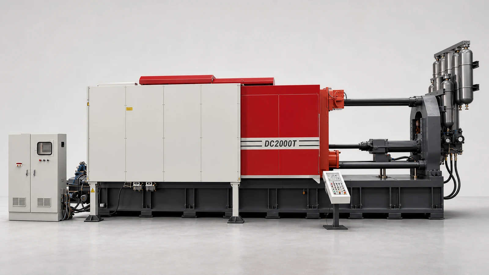
Control station 01 / Fit decision
Use one controlled data set across process, tooling, automation, maintenance, plant engineering, quality, and purchasing. A higher tonnage label cannot compensate for an unresolved shot package, inaccessible die, incomplete utility plan, or untestable acceptance requirement.
Total cavities, runners, overflows, and pressure-exposed slides. Record alloy, projected area, cavity-pressure basis, quality risk, and operating margin before comparing the result with 20,000 kN.
Include net castings, runners, biscuit, overflows, and process allowance. Check the total against one exact plunger package while preserving required intensification pressure.
Verify 600–1,600 mm die thickness, overall size, weight, platen mounting, opening, ejection, slides, core pulls, hoses, vacuum, lifting, insertion, and removal.
Define fill profile, velocity, pressure, metal and die temperatures, vacuum, spray, thermal balance, defect limits, inspection plan, traceability, and approved process capability evidence.
Time furnace, dosing, spraying, extraction, quench, trim, conveyors, inspection, scrap return, recovery, guarding, I/O handshakes, and manual intervention as one cycle.
Freeze transport, rigging, foundation, crane coverage, access, floor loading, power, cooling, air, exhaust, oil-temperature control, drainage, maintenance, and safety zones.
Normalize inclusions, exclusions, interfaces, documentation, spares, packing, Incoterm, installation, training, warranty, FAT, SAT, open actions, and change ownership.
Control station 02 / Shot-end envelope
Published DC2000T data gives boundary ranges, not a complete set of paired shot packages. Do not infer intermediate values. Require the quotation to list aluminum and magnesium capacity, intensification pressure, casting area, sleeve dimensions, injection datum, and interfaces for every offered plunger diameter.
Choose the smallest confirmed package that clears complete shot while retaining the required pressure and documented process margin.
Control station 03 / Published specification console
Use these values for model screening and RFQ preparation. Final design release requires supplier drawings, datums, tolerances, component schedules, utilities, foundation loads, interfaces, software scope, and acceptance conditions.
*Published injection-position values require confirmation of sign convention, reference face, centerline, tolerance, and available positions on the approved machine drawing.
Published manufacturer reference: ShiMi DC2000T Standard Cold Chamber Die Casting Machine. Use this public record to cross-check the web summary; approved supplier drawings and the signed technical agreement govern the final configuration.
Control station 04 / Casting-cell orchestration
A 130 ton machine cannot be evaluated independently from molten-metal delivery, extraction, finishing, safety, data, and recovery. Freeze who supplies, integrates, programs, tests, documents, and supports every interface.
Furnace, transfer, temperature, treatment, dosing accuracy, fill confirmation, alarms, and safe recovery.
Thermal control, spray, blow-off, vacuum, core pulls, sensing, movement, services, and changeover.
Clamp, shot profile, pressure, ejection, recipes, interlocks, traceability, diagnostics, and machine safety.
Extraction, quench, cooling, marking, conveyors, rejection, robot reach, payload, collision zones, and recovery.
Trim, deburr, inspection, leak test, data capture, packing, scrap segregation, and quality release.
Control station 05 / System close-ups
These cleaned reference views support early interface discussions. They do not replace final supplier drawings or approve a particular component make, guard, hose route, control package, option, or service clearance.
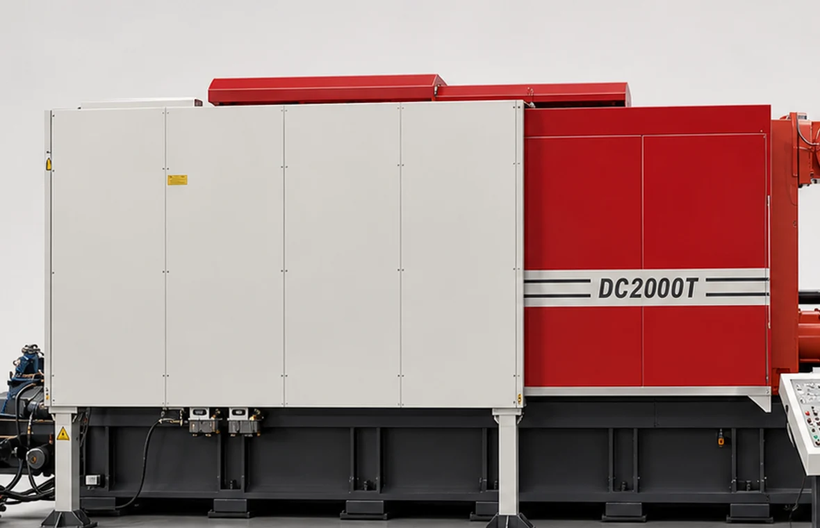
Use this zone to freeze die entry, mounting, tie-bar clearance, moving and fixed-side services, ejection, core pulls, cooling, vacuum, guarding, access doors, lifting points, isolation, and the maintenance corridor. The 1,350 x 1,350 mm opening is only one boundary; the full die and movement envelope must be approved from drawings.
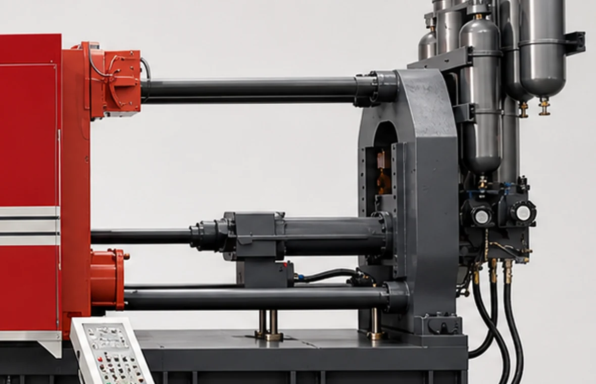
Confirm the exact 120-160 mm shot-end offering, sleeve and plunger interfaces, injection datum, accumulator safe-discharge method, gauges, pressure and velocity measurement, inspection access, hydraulic component schedule, critical spares, and acceptance evidence before the production cell is released.
Control station 06 / 130-ton site release
The published 12.7 × 4.4 × 4.4 m envelope describes the bare machine, not the installed cell. Request transport configuration, shipping weights, centers of gravity, lift points, anchor loads, reactions, utility loads, heat rejection, and maintenance clearances from the final build.
Survey port, road, gates, turning radii, floors, pits, overhead restrictions, unloading area, crane or gantry plan, lifting accessories, staging, and weather protection.
Approve geotechnical assumptions, slab and pit design, static and dynamic loads, anchor pattern, grouting, leveling, oil containment, drainage, vibration, and survey datums.
Reserve crane coverage, die truck route, platen access, shot-end removal, accumulator inspection, lubrication, electrical and hydraulic service, guarding, escape, and rescue zones.
Confirm voltage, frequency, available fault current, grounding, cooling-water quality and duty, compressed air, exhaust, oil cooling, network, lighting, ambient limits, and isolation points.
Control station 07 / Acceptance data room
FAT proves the agreed machine and cell scope under stated factory conditions; SAT confirms installation, interfaces, safety, performance, and documentation at the buyer's site. Neither test should rely on undefined “normal operation.”
Control station 08 / Buyer FAQ
Use these answers for early screening. Put project calculations, drawings, owners, tolerances, interfaces, test conditions, and acceptance evidence into the controlled technical agreement.
The DC2000T is an initial candidate for large aluminum or magnesium projects whose calculated clamp demand, complete shot, required pressure, die envelope, movement, automation, and plant interfaces fit the published 20,000 kN platform. Nominal tonnage alone does not approve a casting, die, cycle, or factory layout.
Published data lists 20,000 kN clamping force, 1,400 mm clamping stroke, 650 kN ejecting force, 300 mm ejection stroke, 600-1,600 mm die thickness, 2,150 x 2,150 mm platens, 1,350 x 1,350 mm tie-bar spacing, 1,510 kN injection force, 1,050 mm injection stroke, 110 kW motor power, a 2,800 L oil tank, and approximate 130 ton machine weight.
Published boundaries cover 120-160 mm plunger diameters, 22-39 kg aluminum shot, 15.8-28 kg magnesium shot, 133-75 MPa intensification pressure, and 1,400-2,630 cm2 casting area. Request the exact paired values for every offered diameter and approve complete shot and required pressure together; do not interpolate a purchase configuration from range endpoints.
Total the pressure-exposed projected area of cavities, runners, overflows, and slides, multiply by the agreed cavity-pressure basis, and apply the documented operating margin. Compare that result with 20,000 kN separately from shot capacity, die fit, and the published 5,000 cm2 maximum casting area.
Approve the shipping split, route survey, unloading and rigging study, center of gravity, crane coverage, foundation, anchoring, floor loads, 12.7 x 4.4 x 4.4 m bare-machine envelope, die-change route, maintenance zones, utilities, cooling, exhaust, guarding, and every peripheral footprint from final supplier drawings.
Require the selected shot end, controls, hydraulics, core pulls, cooling and vacuum interfaces, furnace and automation ownership, safety scope, utilities, drawings, software backups, manuals, spares, packing, installation, training, warranty, exclusions, and change-control route. FAT and SAT must define test conditions, instruments, data, pass criteria, corrective actions, and retest responsibility.
DC2000T controlled project dossier
A useful response should state model fit, the exact shot-end package, preliminary interfaces and layout, utility basis, acceptance path, commercial boundary, open assumptions, and the owner and due date of every next action.
Alloy, drawings, projected area, cavity-pressure basis, cavities, net weight, runners, biscuit, overflows, complete shot, fill profile, quality, inspection, and traceability.
Dimensions, 600–1,600 mm fit, weight, mounting, opening, ejection, slides, core pulls, cooling, vacuum, lifting, storage, and changeover.
Cycle definition, annual volume, shifts, OEE basis, furnace, dosing, spray, extraction, quench, trim, inspection, scrap, guarding, I/O, data, and recovery.
Layout, route, foundation, crane, utilities, safety standard, destination, Incoterm, FAT, SAT, documents, installation, training, warranty, and spares.