Projected area and pressure
Total every cavity, runner, overflow, and pressure-exposed slide. Multiply by the documented cavity pressure and apply the agreed operating margin before comparing with 5,500 kN.
Evidence: calculation sheet
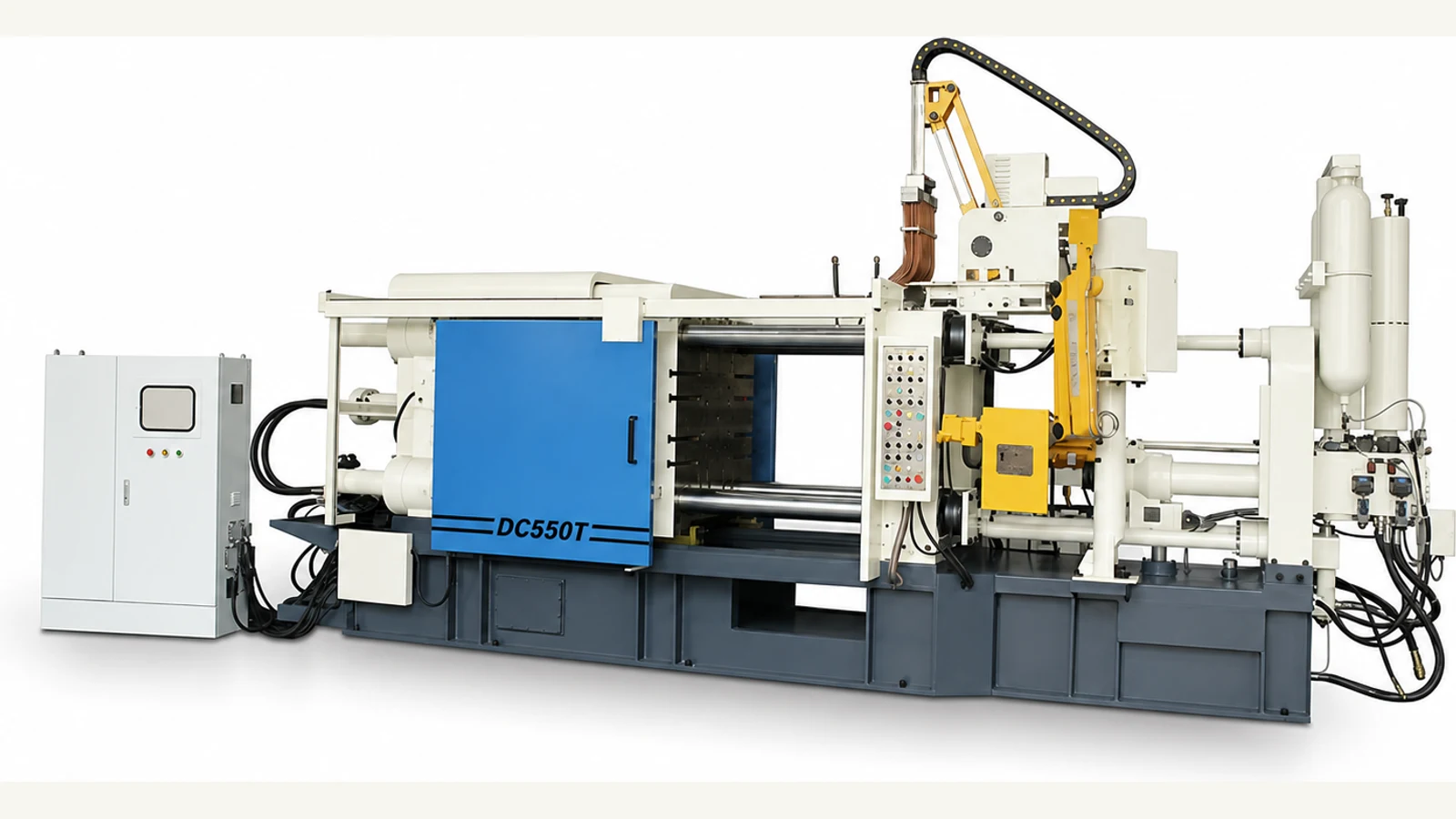
DC550T / Aluminum and magnesium cold chamber platform
The DC550T pairs a published 5,500 kN clamp with a 780 x 780 mm tie-bar opening and three linked pressure-capacity packages. Shortlist it only when the same approved project data clears clamp demand, complete shot, die movement, process pressure, plant access, automation, and acceptance requirements.
Published DC550T data reviewed August 9, 2026 by Cathy, Director. Approved drawings and the signed technical agreement take precedence.
Capacity passport
A 550 ton label is useful for navigation, not engineering approval. Purchasing, process, tooling, automation, maintenance, and plant teams should sign off the same inputs and the same proposed configuration.
Use the machine RFQ checklist →Total every cavity, runner, overflow, and pressure-exposed slide. Multiply by the documented cavity pressure and apply the agreed operating margin before comparing with 5,500 kN.
Evidence: calculation sheetInclude net castings, runners, biscuit, overflows, and process allowance. Match that total to aluminum or magnesium capacity at the required intensification pressure.
Evidence: selected shot packageVerify width, height, 350-850 mm thickness, weight, mounting, opening, ejection, core pulls, cooling, vacuum, lifting route, and service connections.
Evidence: approved interface drawingPlace the 7.5 x 1.95 x 2.8 m machine inside a complete guarded cell with furnace, dosing, spray, extraction, trim, utilities, access, and maintenance zones.
Evidence: signed layout and scopeShot package load chart
The 70, 80, and 90 mm packages are linked engineering choices. Do not specify the largest plunger by default: confirm complete shot, fill profile, required cavity pressure, injection position, sleeve design, alloy, and quality target together.
Highest listed pressure and the lowest complete-shot allowance.
Middle package for a balanced pressure-capacity requirement.
Largest listed shot allowance and the lowest listed intensification pressure.
This is not an automatic part-size approval. Actual allowable projected area depends on geometry, cavity pressure, alloy, quality requirement, and operating margin. Complete shot and die fit remain separate pass/fail checks.
Controlled technical record
Use the values below for model comparison and RFQ preparation. Ask the quotation and approved drawings to confirm datums, tolerances, components, options, interfaces, utility conditions, and the final installation envelope.
Technical reference: current published DC550T product data, reviewed August 9, 2026 by Cathy, Director | *Confirm the injection-position datum and usable range in the project drawing | Final signed technical agreement takes precedence.
Published manufacturer reference: ShiMi DC550T Standard Cold Chamber Die Casting Machine. Use this public record to cross-check the web summary; approved supplier drawings and the signed technical agreement govern the final configuration.
Machine-zone inspection
Both views come from the cleaned DC550T reference image. They identify discussion zones, not guaranteed component brands, quantities, guarding, or included automation.
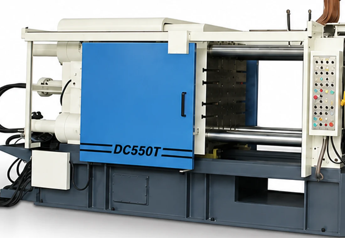
Use this view to review the 780 x 780 mm tie-bar opening, die entry route, mounting and clamping method, ejector and core-pull interfaces, hose routing, operator sightline, guarding boundary, and maintenance-door clearance. The image supports discussion; approved drawings define the supplied arrangement.
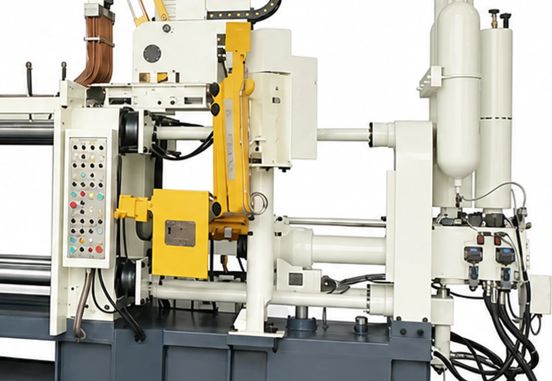
Confirm the selected 70, 80, or 90 mm shot package, injection-position datum, accumulator inspection and safe-discharge method, gauges, hydraulic component makes, access for sleeve and plunger service, and the critical spares included with the order.
Heavy-platform installation gate
Compared with the published 17 ton DC400T, the DC550T is approximately 25 tons and has a larger machine envelope. That step changes handling, access, floor, utility, guarding, and maintenance planning even before peripherals are added.
Confirm port and inland restrictions, packing dimensions, unloading equipment, door and aisle clearances, crane capacity and hook height, lifting points, rigging method, center of gravity, and responsibility for positioning.
Review floor loading and anchoring with the approved foundation drawing. Reserve access for die change, tie-bar and platen service, accumulator inspection, filters, pumps, electrical panels, guarding, and safe escape routes.
State voltage and frequency, transformer boundary, connected and operating loads, cooling-water quality and flow, compressed air, oil-temperature control, fume extraction, furnace energy, and points of connection.
Freeze furnace and dosing height, sprayer and extractor reach, grippers, trim and scrap routing, guard footprint, interlocks, I/O list, fault recovery, safety standard, and validation responsibility before layout approval.
FAT evidence register
A useful FAT plan identifies the test condition, instruments, tolerances, records, sample die and material, attendees, pass criteria, open-item rules, and retest responsibility. A general statement that the machine completed a cycle is not enough.
Match model, serial records, drawings, component list, selected shot package, options, manuals, backups, spares, labels, safety devices, and supply exclusions with the signed agreement.
Observe clamp stages, low-pressure die protection, ejection, lubrication, core pulls, alarms, recovery, injection stages, pressure build, position feedback, recipe recall, and repeatability records.
Test furnace or dosing, spray, extraction, conveyors, trim, guarding and upstream/downstream signals under normal, stopped, interlocked, and recovery conditions.
Close corrective actions; reconcile loose items and preservation; approve packing, lifting and installation instructions; and schedule commissioning, training, warranty support, and remaining performance trials.
DC550T procurement FAQ
These answers are written for cross-functional buying teams. Keep the final casting, process, die, factory, and commercial assumptions in one controlled RFQ package.
The DC550T is an initial candidate for aluminum or magnesium projects whose calculated clamp demand, complete shot, die envelope, process pressure, and cell interfaces fit its published 5,500 kN clamp and a confirmed 70, 80, or 90 mm plunger package. The nominal 550 ton class alone does not approve a casting.
Published data lists 5,500 kN clamping force, 600 mm clamping stroke, 315 kN ejecting force, 120 mm ejection stroke, 350-850 mm die thickness, 1,160 x 1,160 mm platens, 780 x 780 mm tie-bar spacing, 460 kN injection force, 600 mm injection stroke, a 30 kW motor, and an approximate machine weight of 25 tons.
Match complete metal demand and required intensification pressure together. Published aluminum allowances increase from 4.3 to 7.0 kg as plunger diameter rises, while listed intensification pressure decreases from 122 to 74 MPa. Select the package that satisfies both the capacity and pressure window with an agreed process margin.
Total the projected area of every cavity, runner, overflow, and pressure-exposed slide, multiply it by the documented cavity-pressure assumption, and apply the agreed operating margin. Compare the result with 5,500 kN separately from complete shot, the 1,250 cm² published maximum casting area, and die fit.
Compare the DC400T when it clears the same project with margin and a smaller installed scope. Review the DC880T or DC1000T when clamp demand, complete shot, the 780 x 780 mm opening, 850 mm maximum die thickness, die handling, automation reach, or service clearance crosses a documented DC550T limit.
Send the alloy, part and runner drawing, projected area, cavity-pressure assumption, complete shot, cavities, die dimensions and weight, core pulls, target cycle and volume, furnace, dosing, spraying, extraction and downstream plan, utilities, safety standard, destination, and documentation needs. The FAT plan should define safety, motion, injection, repeatability, interfaces, records, pass criteria, and corrective actions.
DC550T model-fit dossier
A drawing plus controlled process, die, cell, and factory data is the fastest route to a defensible model recommendation and a comparable commercial scope.
Alloy, drawing, projected area, cavity-pressure basis, cavities, net weight, complete shot, quality and traceability target.
Dimensions, thickness, weight, mounting, opening, ejection, slides, core pulls, cooling, vacuum, lifting and changeover.
Cycle and volume, furnace, dosing, spray, extraction, trim, inspection, scrap, guarding, interfaces and recovery.
Layout, access route, floor, power, water, air, exhaust, safety standard, destination, FAT, packing, installation and training.